 EN
EN

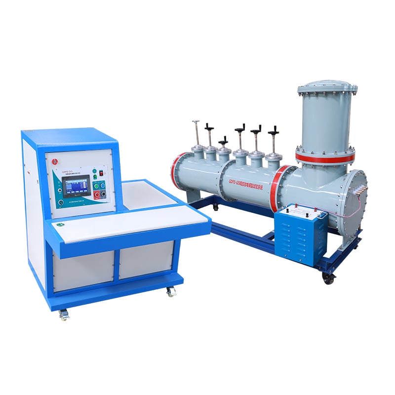
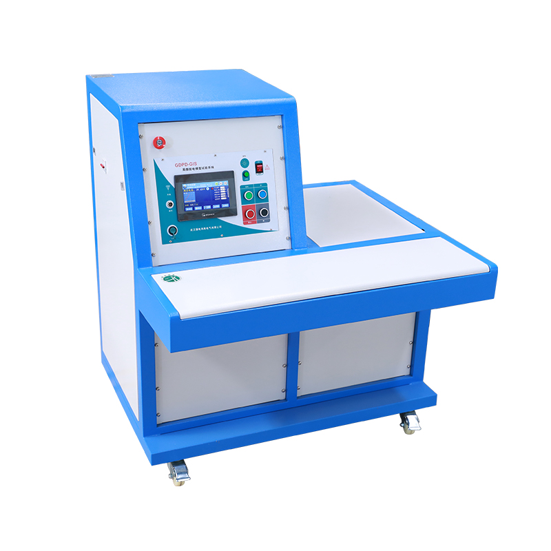
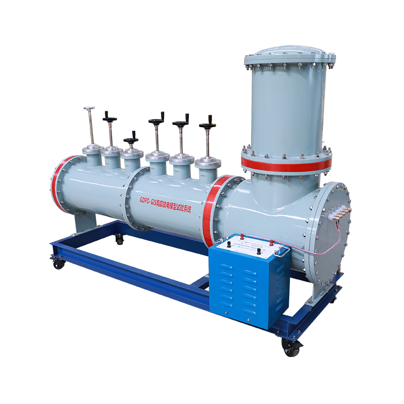
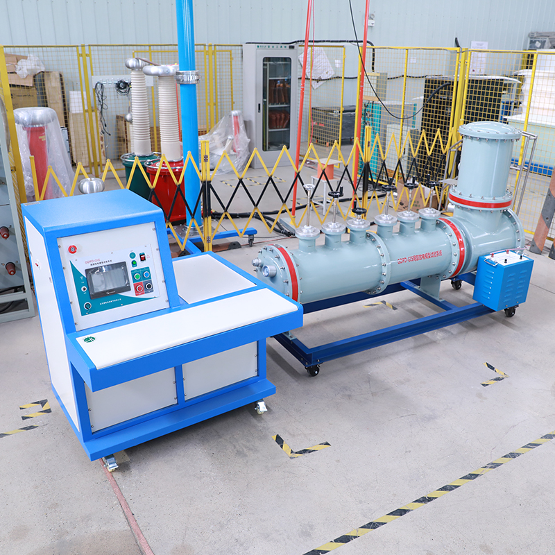
PDS-GIS GIS Partial Discharge Fault Simulation Test System
PDS-GIS Full-Size GIS Partial Discharge Model Test System with SF₆ Sealed Chamber, 5 Typical Insulation Defect Models, Multi-Detection Interface, for PD Mechanism Research, Equipment Calibration and Operator Training.
- Description
- Specifications
- Applications
- Advantages
- FAQ
- Recommended Products
Description
PDS-GIS is a professional full-size GIS partial discharge simulation test platform designed for partial discharge mechanism research, detection equipment performance verification, operator skill training and PD fingerprint database establishment in power research institutes, universities, high-voltage equipment manufacturers, power training centers and third-party testing institutions. It strictly complies with IEC 60270, GB/T 7354-2003 and DL/T 1630-2016 standards, adopting a horizontally arranged true GIS sealed chamber filled with SF₆ gas that truly restores the internal insulation structure and operating environment of actual GIS equipment.
The system integrates 5 classic GIS insulation defect models including metal tip, floating potential, internal air gap, free metal particle and insulator surface discharge, with continuously adjustable discharge magnitude and good repeatability. Its ultra-low background partial discharge (≤1pC) ensures the authenticity and accuracy of test signals. It is fully compatible with mainstream PD detection methods including pulse current method, ultra-high frequency (UHF) method, ultrasonic method and high frequency current transformer (HFCT) method, with reserved standard interfaces for various sensors, supporting comparative test and multi-method joint detection research.
Specifications
| Parameter | Specification |
|---|---|
| Compliance Standards | IEC 60270, GB/T 7354-2003, DL/T 1630-2016, DL/T 417-2006, GB/T 11023-2018 |
| Rated Voltage | 110kV power frequency AC |
| Power Frequency Withstand Voltage | 150kV / 1min |
| Background Partial Discharge | ≤1pC (under rated voltage, no defect input) |
| Chamber Structure | Horizontal aluminum alloy sealed GIS simulation chamber |
| Insulation Medium | SF₆ gas (0.3~0.5MPa working pressure) |
| Annual Air Leakage Rate | ≤0.5% |
| Built-in Defect Types | 5 types: metal tip, floating potential, internal air gap, free metal particle, insulator surface discharge |
| Discharge Magnitude Range | Tip: 5~800pC; Floating: 100~20000pC; Air gap: 10~1000pC; Particle: 0.1~10pC; Surface: 10~1000pC |
| Defect Control Mode | Independent external switching, continuous intensity adjustment |
| Supported Detection Methods | Pulse current method, UHF method, ultrasonic method, HFCT method |
| Standard Interfaces | Pulse calibration port, UHF sensor port (2), ultrasonic detection window, HFCT ground wire port, coupling capacitor interface |
| Coupling Capacitance | 50pF built-in |
| Pressure Measurement | Precision SF₆ pressure gauge with temperature compensation |
| Protection Functions | Over-voltage, over-current, pressure relief valve, reliable grounding |
| Chassis Form | Integrated mobile chassis with universal casters and leveling feet |
| Operating Temperature | 0℃ ~ +40℃ |
| Humidity | ≤85% RH (non-condensing) |
| Overall Dimensions | ~2800 × 800 × 1200mm (L×W×H) |
| Total Weight | ~850kg |
| Enclosure Material | High-strength aluminum alloy + surface anodizing |
Applications
Core Application Scenarios
- Equipment calibration & verification: Performance calibration, sensitivity verification and index detection of various partial discharge testers
- Practical operation training: Skill training and assessment for power operation and maintenance personnel, defect pattern recognition training
- Discharge mechanism research: Basic research on GIS partial discharge characteristics, propagation law and defect evolution process
- Fingerprint database establishment: Collection of standard PRPD patterns of various defects, construction of AI identification sample database
- Teaching experiment: Undergraduate and graduate teaching experiments in electrical engineering majors
Typical Users
- Power research institutes: High-voltage test laboratories, power science research institutes
- Colleges & universities: Electrical engineering departments, key laboratories of high voltage and insulation
- PD equipment manufacturers: Factory calibration and performance test of partial discharge detection instruments
- Power training centers: Skill training and assessment of operation and maintenance personnel, live detection training base
- Third-party testing institutions: Instrument calibration, testing method research and standard verification
Advantages
Compliance with International & Industry Standards
Fully meets IEC 60270, DL/T 1630, GB/T 7354 → test data is traceable, and test results are authoritative and comparable
True GIS Structure & Ultra-Low Background Discharge
SF₆ gas insulated full-size chamber, ≤1pC background noise → truly restores on-site discharge characteristics, ensures signal authenticity
5 Classic Defects & Wide Discharge Range
Covers all common GIS insulation faults, discharge magnitude from 0.1pC to 20000pC → one system meets various test requirements from micro-discharge to severe fault
Full Detection Method Compatibility
Supports pulse current/UHF/ultrasonic/HFCT multi-method joint test → can be used with various PD testers for comparative research and equipment calibration
Stable & Repeatable Discharge Characteristics
High-precision electrodes, adjustable discharge intensity, good long-term stability → suitable for long-term mechanism research and batch calibration test
FAQ
Q: What types of GIS partial discharge defects can this system simulate?
A: PDS-GIS integrates 5 classic GIS insulation defect models, covering almost all common fault types in actual operation:
- Metal tip discharge: simulates conductor burrs and installation scratches
- Floating potential discharge: simulates ungrounded metal components
- Internal air gap discharge: simulates epoxy insulator internal manufacturing voids
- Free metal particle discharge: simulates conductive contaminants left during installation
- Insulator surface discharge: simulates surface contamination and moisture faultsEach defect can be independently switched, and also supports composite defect superposition test.
Q: What is the significance of ≤1pC background partial discharge?
A: Background discharge is the inherent discharge of the test system itself. If the background is too high, it will submerge the weak defect signal and affect the authenticity and accuracy of the test. The ≤1pC ultra-low background of PDS-GIS can ensure that the detected signal completely comes from the defect model, and can stably detect micro-discharge as low as 0.1pC, which meets the requirements of high-sensitivity test and equipment calibration.
Q: Which partial discharge detection methods can be supported?
A: The system fully supports 4 mainstream GIS PD detection methods:
- Pulse current method: standard IEC 60270 quantitative detection
- UHF method: ultra-high frequency electromagnetic wave detection
- Ultrasonic method: acoustic vibration detection
- HFCT method: high frequency current detection on grounding wireReserved standard installation interfaces for each detection method, which can be used with various brands of PD testers for calibration and comparative test.
Q: Can this system be used to calibrate partial discharge testers?
A: Yes. PDS-GIS is equipped with a standard pulse injection port, which can be connected to a PD calibrator for quantitative calibration. The discharge magnitude of each defect model is continuously adjustable and has good repeatability, which can be used as a standard signal source to verify the detection sensitivity, measurement accuracy and defect recognition ability of various PD testers.